Finding the muon stopping site with pymuon-suite in Galaxy
| Author(s) |
|
| Editor(s) |
|
| Reviewers |
|
OverviewQuestions:
Objectives:
What are stopping sites and why is finding them important?
What computational techniques can be used to find stopping sites?
How can Galaxy help me with my analysis?
Requirements:
Understand why finding stopping sites is useful
Use pymuon-suite in Galaxy to find stopping sites
Understand the limitations of these tools and techniques
Time estimation: 1 hourLevel: Introductory IntroductorySupporting Materials:Published: Jan 22, 2024Last modification: Jun 14, 2024License: Tutorial Content is licensed under Creative Commons Attribution 4.0 International License. The GTN Framework is licensed under MITpurl PURL: https://gxy.io/GTN:T00402version Revision: 2
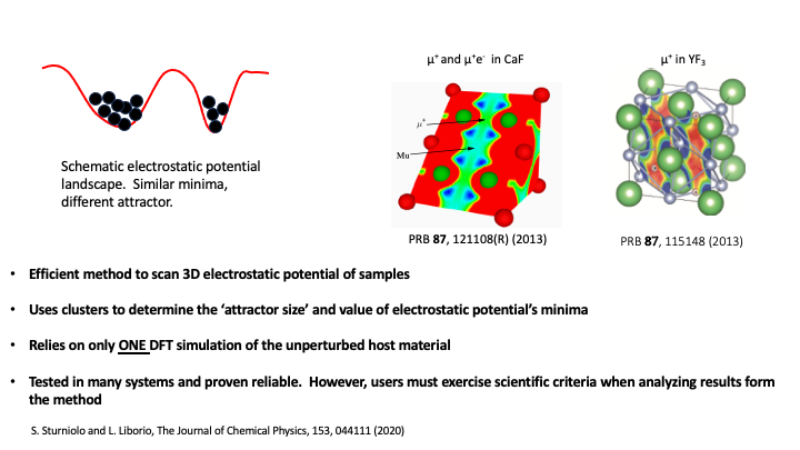
The problem of identifying the stopping site of the muon is often key in the interpretation of muon experimental results. As it was mentioned in the lecture, the problem of finding the muon stopping site has been previously tackled using computational tools, and one of the most common methods is the so-called Unperturbed Electrostatic Potential (UEP) method, which identifies proposes that the muon stops at the minima of the UEP of a crystalline host material.
pymuon-suite in Galaxy implements a variant of the UEP, that allows the users to efficiently scan the UEP of the host material and use a clustering procedure to classify those minima as potential stopping sites. But, before moving into the details of how the method works, it is useful to revisit some of the key assumptions behind what happens in a muon experiment.
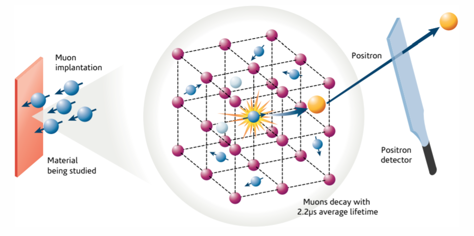
At the atomic level, muon spectroscopy experiments go something like this:
- A spin-polarized muon beam of positive muons is fired at the sample
- Through inelastic collisions with the atoms of the crystalline host material, muons shed their kinetic energy, which turns into heat or causes small amounts of damage to the crystal. This continues until the muons’ kinetic energy becomes low enough that it is comparable to their potential energy in the electrostatic potential generated by electrons and nuclei alike.
- At that point, Coulomb forces start driving the muon, until it eventually loses as much energy as possible and comes to a stop in a position that sometimes represents a local (and possibly global) minimum for the sample’s UEP energy. Once it stopped, the muon may spend the rest of its time in that position until it decays.
Where these minima of the potential actually are isn’t always obvious and, although the our version of the UEP method has proven to be quite efficient and useful, there are certain crystalline materials where predicting the minima of the UEP potential can be a lot harder. For instance, in lithium fluoride Liborio et al. 2018, the potential’s minima are flat and wide and current computer simulations fail to predict the muon stopping site. Hence, users must exercise scientific criteria when analyzing results form the method
This tutorial goes into the details of how to estimate the muon stopping site in crystalline copper, as described in the lecture, and it assumes that some basic Galaxy concepts such as: how to upload a file; how to use a Galaxy tool; how to create, view and share a history and how to extract and run a Galaxy workflow, are known. Hence, as stated in the requirements at the beginning of this tutorial please, before starting have a look at this: A short introduction to Galaxy
AgendaIn this tutorial, we will cover:
Workflow for Finding the µ+ stopping site
As described in the lecture, the full workflow associated with finding potential muon stopping sites in crystalline copper is shown in the figure below:
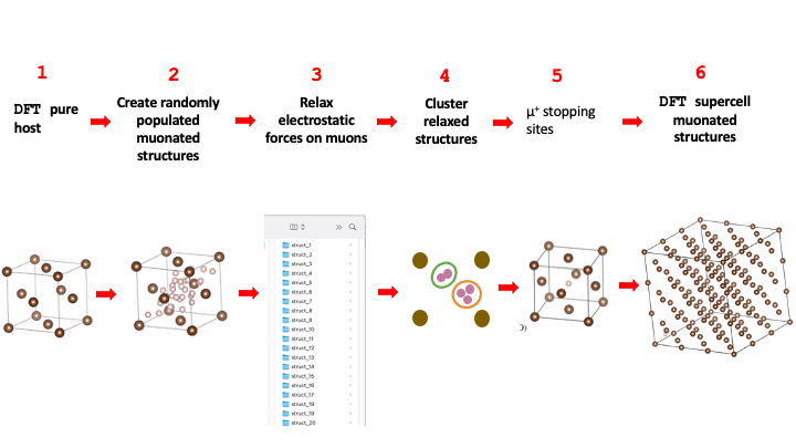
It comprises 6 steps that will be described in detail in the next sections. Steps 1 and 6
are performed outside of the Galaxy platform, usually in an external computer cluster that can
run the necessary Density Functional Theory (DFT) simulations. Steps 2, 3, 4, and 5 of this workflow are are carried out
in Galaxy using two Galaxy tools: PyMuonSuite AIRSS UEP Optimise and PyMuonSuite AIRSS Cluster.
Hence, there is a difference between the full workflow and the specific Galaxy part of this workflow, which can be saved, shared and edited in the Galaxy platform. For the case of finding potential muon stopping sites in crystalline Cu, the components of Galaxy workflow are shown below:
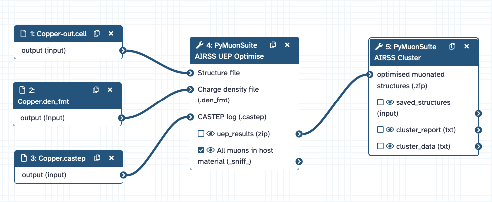
And this is the workflow that can be imported for this tutorial.
Import workflow
Hands On: Import workflow
- Import the workflow for this tutorial using these instructions.
- Open the editor for the workflow, and verify that all the required tools are installed on your Galaxy instance, and have the same version(s) as the tools in workflow. If this is not the case a dialogue box will warn you.
DFT calculation of the Pure Host Material
This method requires only a single DFT calculation for the host material. This calculation could be a geometry optimisation, which uses a self-consistent methodology to estimate the electronic structure of the material and relax the structure. Pymuon_suite uses the CASTEP code for running its DFT calculations, and some basic information about how to run a geometry optimisation is available in the CASTEP documentation.
Once the relaxed structure and its corresponding electronic structure are obtained,
a set of CASTEP output files is generated. We need to load just three of these files
into Galaxy. These are the relaxed CASTEP structural file *-out.cell, the
charge density file *.den_fmt and the CASTEP output file *.castep.
The CASTEP files for this example have all been pre-generated for this tutorial, but in general you would need to create these yourself by running CASTEP simulations outside of Galaxy.
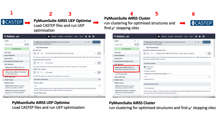
To run the first part of the workflow, on the left menu of the Galaxy web-page
we look for the FIND MUON STOPPING SITES header and first click on UEP method and then
select the PyMuonSuite AIRSS UEP Optimise Galaxy tool. This brings up the central panel of the Galaxy
web-page, where can load the CASTEP files; complete the Generation parameters to set up the
creation of randomly populated muonated structures; and complete the Optimisation parameters to set up the relaxation the
electrostatic forces of the muon in each of the randomly populated muonated structures.
How to load CASTEP files into Galaxy
Hands On: Data upload
- Create a new history for this tutorial
Import the files from Zenodo, from you computer, or from the shared data library (
GTN - Material->materials-science->Finding the muon stopping site with pymuon-suite in Galaxy):https://zenodo.org/records/10219558/files/Cu-out.cell https://zenodo.org/records/10219558/files/Cu.castep https://zenodo.org/records/10219558/files/Cu.den_fmt
- Copy the link location
Click galaxy-upload Upload at the top of the activity panel
- Select galaxy-wf-edit Paste/Fetch Data
Paste the link(s) into the text field
Press Start
- Close the window
As an alternative to uploading the data from a URL or your computer, the files may also have been made available from a shared data library:
- Go into Libraries (left panel)
- Navigate to the correct folder as indicated by your instructor.
- On most Galaxies tutorial data will be provided in a folder named GTN - Material –> Topic Name -> Tutorial Name.
- Select the desired files
- Click on Add to History galaxy-dropdown near the top and select as Datasets from the dropdown menu
In the pop-up window, choose
- “Select history”: the history you want to import the data to (or create a new one)
- Click on Import
- Rename the datasets to match their file names, if needed.
Check that the datatype is correct for each dataset.
- Click on the galaxy-pencil pencil icon for the dataset to edit its attributes
- In the central panel, click galaxy-chart-select-data Datatypes tab on the top
- In the galaxy-chart-select-data Assign Datatype, select
datatypesfrom “New Type” dropdown
- Tip: you can start typing the datatype into the field to filter the dropdown menu
- Click the Save button

Create Randomly Populated Muonated Structures
The first step within the Galaxy platform is the population of the host material’s interstitial spaces with muons that are randomly distributed in accordance with certain physical constraints.
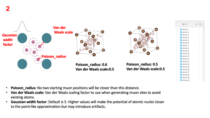
Essentially, the muons are randomly distributed while respecting
a minimum distance between them and between the atoms
in the host material. The Poisson radius parameter sets the minimum spacing
between the muons that are randomly implanted in the sample, while the
Van der Waals scale parameter sets the minimum spacing between randomly
implanted muons and the atoms in the host material. Two of the images in the figure
above show how the density of distributed muons changes for different values of
the Poisson radius. These images are just for visualization purposes, what
the method really does is generate a set of muonated structures, where each one has a muon
in a different place, and place each muonated structure in a corresponding folder.
Relax Electrostatic Forces on Muons
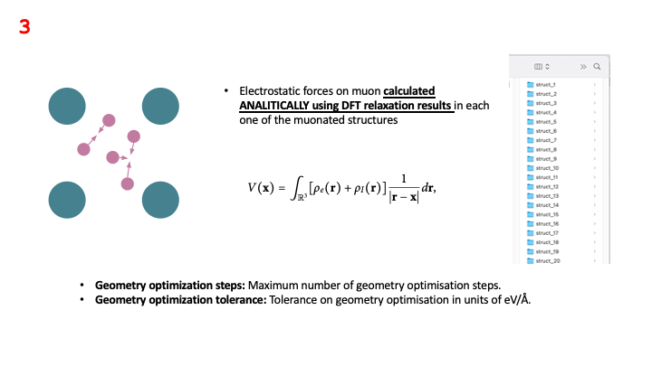
As stated in the lecture, the method minimizes the electrostatic forces acting on the muon in each of the
muonated structures generated in the previous step. In this relaxation procedure,
the forces are calculated analytically using data obtained from the DFT simulation of the unperturbed host material:
the charge density file *.den_fmt, the relaxed CASTEP structural file *-out.cell, the and the CASTEP output file *.castep,
and then the muon is displaced in a direction
that minimizes the forces acting upon it. This is a self-consistent procedure, which is repeated until the
forces on each muon are below the value specified in the geometry optimisation tolerance parameter, or until
the maximum number of geometry optimisation steps is reached.
This workflow’s step could be computationally expensive. The larger the
the size of the host material’s unit cell, and the smaller the values of Poisson radius and
Van der Waals scale parameters, the larger number of muonated structures created, and the
more expensive this step will be. In any case: the relaxation procedure is run in the Galaxy
server, so the user can just start it and leave it running in the Galaxy instance. The status of
the relaxation will be indicated in the history panel on the right menu of the Galaxy web-page, where
all the processes run by the Galaxy instance are numbered.
Below, a hands-on example on how to run these workflow steps.
Hands On: PyMuonSuite AIRSS UEP Optimise
- Run the PyMuonSuite AIRSS UEP Optimise ( Galaxy version 0.3.0+galaxy1) tool with the following parameters:
- “Tool Parameters”:
- param-file “Structure file”:
Cu-out.cellrelaxed CASTEP structural file- param-file “Charge density file”:
Cu.den_fmtCASTEP file with charge density of host material- param-file “CASTEP log file”:
Cu.castepThe CASTEP output file for the initial DFT simulation- “Generation Parameters”:
- “Poisson radius”:
0.6Sets the minimum spacing between the muons that are randomly implanted in the sample- “Van der Waals scale”:
0.5Sets the minimum spacing between randomly implanted muons atoms in host material- “Random seed”:
optionalthis is if we want to re-use a set of generated structures. Rarely used- “Format for file containing all muon positions (optional)”:
cellGenerates an extra output file containing all the muon positions- “Optimisation parameters Parameters”:
- “Geometry optimization steps”:
300Maximum number of geometry optimisation steps- “Geometry optimization tolerance”:
0.05Tolerance on geometry optimisation in eV/AA- “Gaussian width factor”:
5.0Adjusts how atom potentials are modelled
Cluster Relaxed Structures - µ+ Stopping Sites
Once the relaxation is over, there will appear a new item on the history panel denominated
PyMuonSuite AIRSS UEP Optimise on data X, data Y and data Z. This item
contains a *.zip file with all the optimised muonated structures, where X, Y and Z are
the numbers of the processes, in the history panel, that were used for running the relaxation
of the electrostatic forces on muons.
The first step for running the clustering procedure is to select the PyMuonSuite AIRSS Cluster Galaxy tool on
the left menu of the Galaxy web-page . This brings up the corresponding central panel of the Galaxy
web-page, where can load the optimised muonated structures *.zip contained in the
PyMuonSuite AIRSS UEP Optimise on data X, data Y and data Z item.
Then we need to select the clustering method and it corresponding parameters. There are two clustering methodologies
available: hierarchical and k-means clustering. We recommend using the hierarchical clustering first, choosing different
values of the t parameter for hierarchical clustering, until a consistent number of clusters is found. Once that
number is found, we can perform a k-means clustering analysis, using the number of hierarchical clustering clusters as
the value for the Number of clusters for k-means clustering parameter.
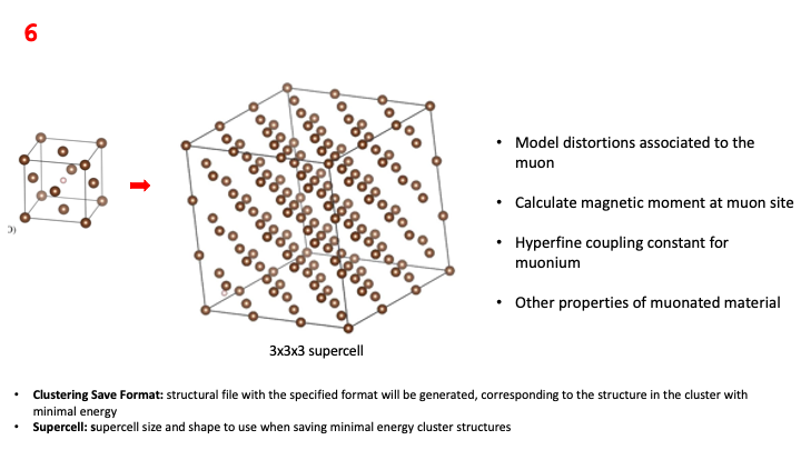
Finally, we need to choose the Clustering Save Format. This allows for the visualisation of the potential stopping sites
associated to each of the clusters found, but it can also be used to prepare the *.cell supercell file that is needed to
run the last step of the workflow: the DFT relaxation of each of the muonated structures associated to each of
the potential stopping sites. The *.cell supercell file can then be downloaded from Galaxy and used to run
a CASTEP DFT simulation, which can be used to analyse things such as the distortions caused by the muon in the host
material.
Below, a hands-on example on how to run this workflow step.
Hands On: PyMuonSuite AIRSS Cluster
- Run the PyMuonSuite AIRSS Cluster ( Galaxy version 0.3.0+galaxy0) tool with the following parameters:
- “Tool Parameters”:
- “optimised muonated structures”:
PyMuonSuite AIRSS UEP Optimise on data X, data Y and data Zload the optimised muonated structures*.zipfile- “Clustering method”:
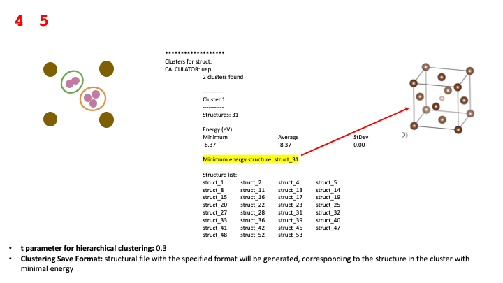
hierarchicalPerforms hierarchical clustering- “t parameter for hierarchical clustering”:
0.2Threshold value for clusters- “Clustering method”:
k-meansPerforms k-means clustering. Needs guess for number of clusters- “Number of clusters for k-means clustering “:
2Proposed number of clusters for k-means. Usually the clusters found withhierarchicalclustering- “Clustering Save Format”:
cellCreates a structural file for each cluster, corresponding to the structure in the cluster with minimal energy, with the specified format- “Supercell”:
3Supercell size and shape to use when saving cluster structures- “Muon symbol”:
H:muThe symbol to use for the muon when writing out the CASTEP custom species. H:mu is the default.
Analysis of the Cluster report
Once the clustering procedure is over, there will appear a new item on the history panel denominated Cluster report for PyMuonSuite AIRSS UEP Optimise on data X, data Y, and data Z, which contains a human-readable summary of the clustering results, with the underlying raw data also provided. The top of the report contains a summary of the settings used to run the clustering, and when it was run.
Code Out: MuAirss Clusters report**************************** | | | PYMUON-SUITE | | MuAirss Clusters report | | | **************************** Name: struct Date: 2023-11-06 09:41:00.787599 Structure file(s): input_structure.cell Parameter file: params.yaml Clustering method: Hierarchical t = 0.4 *******************
The remainder of the report details the clusters and the individual muonated
structures composing each cluster. In
addition to showing the relative numbers of structures forming each cluster,
we also report the structure with the minimum energy, the average energy for all the structures
and the corresponding standard deviation for that average energy. By analysing of these
quantities for different values of the Poisson radius, Van der Waals scale and
t parameter for hierarchical clustering parameters, we can determine which
are the “stable” clusters, which are the ones associated to potential stopping sites.
Code Out: MuAirss Clusters reportClusters for struct: CALCULATOR: uep 2 clusters found ----------- Cluster 1 ----------- Structures: 7 Energy (eV): Minimum Average StDev -10.30 -10.30 0.00 Minimum energy structure: struct_7 Structure list: struct_1 struct_3 struct_5 struct_6 struct_7 struct_8 struct_12 ----------- Cluster 2 ----------- Structures: 7 Energy (eV): Minimum Average StDev -11.93 -11.93 0.00 Minimum energy structure: struct_14 Structure list: struct_2 struct_4 struct_9 struct_10 struct_11 struct_13 struct_14 ---------- Similarity (ranked): 1 <--> 2 (distance = 1.681) --------------------------
The classical UEP method scans the electrostatic potential looking for minima in it, which are associated to potential muon stopping sites. This method further classifies those minima by estimating their “attractor size”. If you look at the picture in the figure below, the two minima have similar values, but the capacity to “attract” a muon is greater for the minima on the left, which makes it more likely to be a muon stopping site. The probability of a potential stopping site is given by the size of the cluster that forms around its associated minima.
You've Finished the Tutorial
Key points
Galaxy supports multiple PyMuonSuite tools which can be used together to find muon stopping sites
The workflow for finding the stopping site involves three stages - structure generation, structure optimisation, and structure clustering
Within the UEP, the optimisation stage is based on analytically calculating the electrostatic forces applied to the muon, which can be performed via Galaxy.
The approach requires a CASTEP DFT calculation to be completed as a starting point
Frequently Asked Questions
Have questions about this tutorial? Have a look at the available FAQ pages and support channelsReferences
- Liborio, L., S. Sturniolo, and D. Jochym, 2018 Computational prediction of muon stopping sites using ab initio random structure searching (AIRSS). The Journal of Chemical Physics 148: 134114. 10.1063/1.5024450
Glossary
- AIRSS
- Ab Initio Random Structure Search
- DFT
- Density Functional Theory
- UEP
- Unperturbed Electrostatic Potential
Feedback
Did you use this material as an instructor? Feel free to give us feedback on how it went.
Did you use this material as a learner or student? Click the form below to leave feedback.

Citing this Tutorial
- Leandro Liborio, Eli Chadwick, Patrick Austin, Finding the muon stopping site with pymuon-suite in Galaxy (Galaxy Training Materials). https://training.galaxyproject.org/training-material/topics/materials-science/tutorials/muon-stopping-sites-muairss-uep/tutorial.html Online; accessed TODAY
- Hiltemann, Saskia, Rasche, Helena et al., 2023 Galaxy Training: A Powerful Framework for Teaching! PLOS Computational Biology 10.1371/journal.pcbi.1010752
- Batut et al., 2018 Community-Driven Data Analysis Training for Biology Cell Systems 10.1016/j.cels.2018.05.012
@misc{materials-science-muon-stopping-sites-muairss-uep,
author = "Leandro Liborio and Eli Chadwick and Patrick Austin",
	title = "Finding the muon stopping site with pymuon-suite in Galaxy (Galaxy Training Materials)",
	year = "",
	month = "",
	day = "",
	url = "\url{https://training.galaxyproject.org/training-material/topics/materials-science/tutorials/muon-stopping-sites-muairss-uep/tutorial.html}",
	note = "[Online; accessed TODAY]"
}
@article{Hiltemann_2023,
	doi = {10.1371/journal.pcbi.1010752},
	url = {https://doi.org/10.1371%2Fjournal.pcbi.1010752},
	year = 2023,
	month = {jan},
	publisher = {Public Library of Science ({PLoS})},
	volume = {19},
	number = {1},
	pages = {e1010752},
	author = {Saskia Hiltemann and Helena Rasche and Simon Gladman and Hans-Rudolf Hotz and Delphine Larivi{\`{e}}re and Daniel Blankenberg and Pratik D. Jagtap and Thomas Wollmann and Anthony Bretaudeau and Nadia Gou{\'{e}} and Timothy J. Griffin and Coline Royaux and Yvan Le Bras and Subina Mehta and Anna Syme and Frederik Coppens and Bert Droesbeke and Nicola Soranzo and Wendi Bacon and Fotis Psomopoulos and Crist{\'{o}}bal Gallardo-Alba and John Davis and Melanie Christine Föll and Matthias Fahrner and Maria A. Doyle and Beatriz Serrano-Solano and Anne Claire Fouilloux and Peter van Heusden and Wolfgang Maier and Dave Clements and Florian Heyl and Björn Grüning and B{\'{e}}r{\'{e}}nice Batut and},
	editor = {Francis Ouellette},
	title = {Galaxy Training: A powerful framework for teaching!},
	journal = {PLoS Comput Biol}
}
Funding
These individuals or organisations provided funding support for the development of this resource
Congratulations on successfully completing this tutorial!
You can use Ephemeris's
shed-tools installcommand to install the tools used in this tutorial.shed-tools install [-g GALAXY] [-a API_KEY] -t <(curl https://training.galaxyproject.org/training-material/api/topics/materials-science/tutorials/muon-stopping-sites-muairss-uep/tutorial.json | jq .admin_install_yaml -r)Alternatively you can copy and paste the following YAML
---
install_tool_dependencies: true
install_repository_dependencies: true
install_resolver_dependencies: true
tools:
- name: pm_muairss_read
  owner: muon-spectroscopy-computational-project
  revisions: 40071ff77285
  tool_panel_section_label: Muon Spectroscopy
  tool_shed_url: https://toolshed.g2.bx.psu.edu/
- name: pm_uep_opt
  owner: muon-spectroscopy-computational-project
  revisions: eea73e1f65cb
  tool_panel_section_label: Muon Spectroscopy
  tool_shed_url: https://toolshed.g2.bx.psu.edu/